Mastering Revit Project Coordinates:
The BIM Blueprint for Precision & Seamless Collaboration

Understanding Project Coordinates: The Foundation of Precise Modeling in Revit

In the world of BIM design and construction, precision is everything. A well-coordinated model ensures seamless collaboration across disciplines, minimizes errors, and streamlines workflows. In Autodesk Revit, project coordinates play a pivotal role in achieving this precision. They define the spatial relationship between various elements in a project and connect the digital model to real- world site data.


Skillful management of project coordinates allows you to tackle even the most complex, cross- discipline construction projects with ease. However, even a small, unnoticed shift in model coordinates can lead to inaccurate clash detection results. In more severe cases, such errors can cause models to completely misalign during assembly, leading to significant challenges in project execution. This blog dives into the significance of these critical points, exploring their roles, interconnections, and best practices for managing them in your Revit projects. Whether you’re a beginner or an experienced professional, understanding these fundamentals will empower you to take control of your project’s coordination and elevate the quality of your work.


In Autodesk Revit, there are several essential concepts for managing project coordinates and ensuring accurate collaboration and alignment between various project files. Here’s an explanation of each:

1. Internal Origin (IO)

  1. Definition: The Internal Origin is the fixed, invisible point that defines the origin (0,0,0) of Revit’s internal coordinate system. It cannot be moved or modified. All geometry in the model is positioned relative to this origin.

  2. Characteristics:
  • The Internal Origin ensures numerical precision and consistency within the model. Moving too far from it can cause accuracy issues
  • Typically hidden during modeling but can be displayed for reference.
  • Aligns with the origin of linked files when no additional transformations are applied.

2. Project Base Point (PBP)

  1. Definition: The Project Base Point is a visible reference point that represents the project’s internal zero point. It can be moved and is often used to define a logical starting point for the project (e.g., a corner of the building).

  2. Characteristics:
    • Project basepoint typically has these properties:
      North/South, East/West, Elevation and Angle to True North.

3. Survey Point (SP)

  1. Definition: The Survey Point is a reference point used to define the location of the model relative to a real-world survey coordinate system. This is used to create a “shared coordinates” system among multiple linked Revit or CAD files.

  2. Characteristics:
  • Clipped State:
    • Moving the Survey Point moves the entire model relative to the shared coordinates.
    • Use this when you want to reposition the model without changing the Survey Point’s real-world coordinates.

  • Unclipped State:
    • Moving the Survey Point only updates its real-world coordinates without moving the model.
    • Use this when you need to redefine the Survey Point’s location (e.g., after receiving updated survey data)

4 . True North and Project North

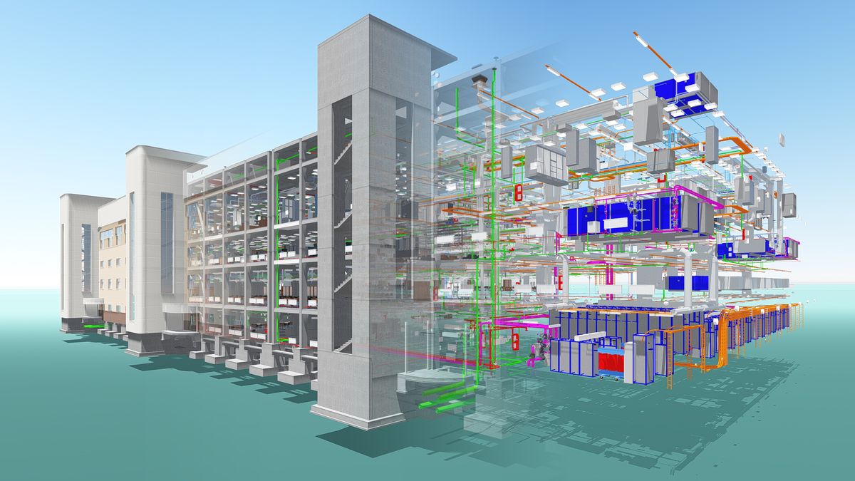
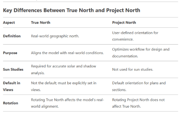
In Revit, True North and Project North are two distinct concepts used to manage the orientation of your model. These tools are essential for aligning your project with real-world conditions (True North) and optimizing your workflow for design and documentation (Project North).
        1. True North: 

          True North represents the real-world geographic north. It is used to orient your model correctly in relation to the actual site conditions.
          • True North ensures that your model aligns with the actual orientation of the site, as determined by survey data or geographic information.
          • True North is critical for accurate sun path analysis and shadow studies, as it reflects the real-world position of the sun.
          • True North is critical for accurate sun path analysis and shadow studies, as it reflects the real-world position of the sun.
          • To Set True North: Go to the Manage tab > Project Location > Position Rotate True North.

        2. Project North:
            

          Project North is a user-defined orientation that simplifies the design and documentation process. It is independent of True North and can be rotated to any angle for convenience.
            • Project North allows you to orient your model in a way that makes drawing, annotating, and documenting easier.
            • By default, Revit uses Project North for views, so your plans and sections align with this orientation.
            • To Set Project North: Go to the Manage tab > Project Location > Position Rotate Project North.

Coordinate Systems in Revit

In Revit, coordinate systems are fundamental for positioning and aligning models. Two key concepts are the Internal Coordinate System and the Shared Coordinate System 

1. Internal Coordinate System:

The Internal Coordinate System is the default coordinate system in Revit, based on the internal Origin. It is used for all internal calculations and positioning within a single model.

2. Shared Coordinate System:

The Shared Coordinate System is a common coordinate system used to align multiple models (e.g., architectural, structural, MEP). It is based on real-world coordinates and ensures that all models are positioned consistently.
When you link models using shared coordinates, Revit aligns them based on the Shared Coordinate System while maintaining their internal coordinate systems.

Ensuring Accurate Positioning of Multiple Models in Revit

Starting a new BIM project with separate architectural, structural, and MEP models requires careful
planning to ensure accurate positioning and coordination. By making the architectural model the
base file for coordinates, you can establish a consistent reference point for all disciplines.

Philosophy for Managing Coordinates:

1. Single Source of Truth:

    • The architectural model will serve as the base file for coordinates.
    • All other models (structural, MEP) will acquire coordinates from the architectural
      model.

2. Consistency Across Models:

    • Ensure all teams use the same shared coordinate system.
    • Avoid moving the Survey Point or Project Base Point unnecessarily.

3. Early Setup:

    • Establish the coordinate system at the beginning of the project to avoid rework.

4. Communication:

    • Clearly communicate coordinate system changes to all teams.
    • Document the coordinate system setup for reference.

Step-by-Step Workflow:

1. Set Up the Architectural Model

         1. Define the Project Base Point and Survey Point:

    • Open the architectural model.
    • Place the Project Base Point at a logical reference point (e.g., a corner of the building).
    • Place the Survey Point at the real-world coordinates (if available from a surveyor).

          2. Set True North:

    • Go to the Manage tab > Project LocationPosition > Rotate True North.
    • Align the model with the real-world north.

         3. Publish Coordinates:

    • Go to the Manage tab > Coordinates Publish > Coordinates.
    • Select the architectural model itself to establish the shared coordinate system.

2. Link the Architectural Model into Structural and MEP Models

         1. Open the Structural or MEP Model:

    • Start a new Revit file for the structural or MEP model.

          2. Link the Architectural Model:

    • Go to the Insert tab > Link Revit.
    • Browse and select the architectural model.
    • Choose Auto – By Shared Coordinates in the positioning options.

         3. Acquire Coordinates:

    • Go to the Manage tab > Coordinates > Acquire Coordinates.
    • Select the linked architectural model to align the structural or MEP model with the architectural model’s shared coordinates.

3. Verify Alignment

         1. Check Levels and Grids:

    • Ensure that levels and grids in the structural and MEP models match those in the architectural model.
    • Use the Copy/Monitor tool to copy and monitor key elements (e.g., levels, grids) from the architectural model.

          2. Check Positioning:

    • Verify that all models are aligned correctly by overlaying them in a 3D view or using coordination tools like Navisworks.

4. Manage Updates

         1. Reload Linked Models:

    • Regularly update and reload the linked architectural model in the structural and MEP models to reflect changes.

          2. Communicate Changes:

    • If the architectural model’s coordinates are updated (e.g., Survey Point moved), inform all teams to reacquire coordinates.

Best Practices for Accurate Positioning

 1. Use Shared Coordinates:

    • Always link models using Auto – By Shared Coordinates to ensure proper alignment.

2. Avoid Moving the Survey Point Unnecessarily:

    • Moving the Survey Point in the architectural model can disrupt the shared coordinate system. Only move it if absolutely necessary.

3. Use Copy/Monitor for Key Elements:

    • Use the Copy/Monitor tool to copy and monitor levels, grids, and other critical elements from the architectural model.

4. Document the Coordinate System:

    • Document the location of the Survey Point, Project Base Point, and True North orientation for reference. 

Contact Us


© Copyright Raywell Studio 2025. All Rights Reserved. Website Designed and Developed by SmartFish